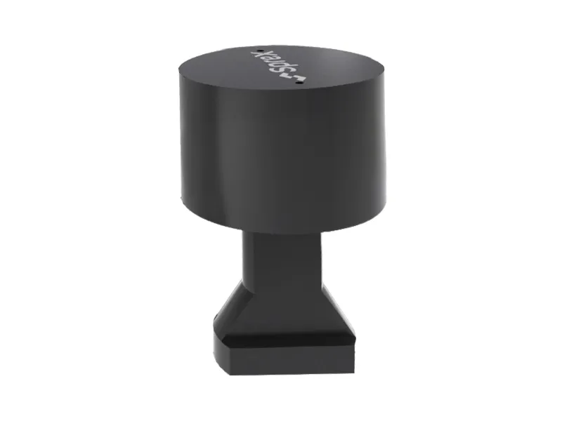
Machine series specifications
- Clamping force (25MP): 20 kn
- X-stroke: 7 mm
- Y-stroke: 3 mm
- Z-stroke safety: 4 mm
- Clamping force (25MP): 40 kn
- X-stroke: 7 mm
- Y-stroke: 3 mm
- Z-safety stroke: 4 mm
- Clamping force (25MP): 60 kn
- X-stroke: 8 mm
- Y-stroke: 4 mm
- Z-safety stroke: 4 mm
- Clamping force (25MP): 100 kn
- X-stroke: 8 mm
- Y-stroke: 3 mm
- Z-safety stroke: 5 mm
- Clamping force (25MP): 160 kn
- X-stroke: 8 mm
- Y-stroke: 3 mm
- Safe Z stroke: 5 mm
- Clamping force (25MP): 250 kn
- X stroke: 8 mm
- Y stroke: 3 mm
- Safe Z stroke: 5 mm
Line | Clamping Force(25MP) | Total Cycle | Clamping Cycle | Safe Cycle | Hydraulic Clamp Cylinder Mass | Weight |
KN | mm | mm | mm | cm3 | kg | |
FY2 | 20 | 8 | 4 | 4 | 6.5 | 2 |
FY4 | 40 | 8 | 3 | 5 | 15 | 4 |
FY6 | 60 | 8 | 3 | 5 | 22 | 6 |
FY10 | 100 | 8 | 5 | 5 | 33 | 8 |
FY16 | 160 | 8 | 5 | 5 | 55 | 10 |
FY25 | 250 | 8 | 5 | 5 | 85 | 18 |
Product selection
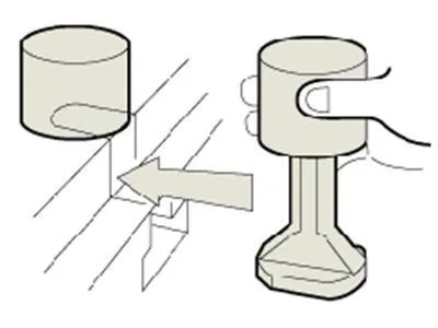
Customers can choose the product line and the corresponding number of clips depending on their usage needs.
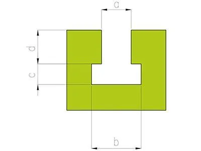
Hydraulic clamping system type | a(H7) | b | c | d | ||
FW2 | FW2-S | FY2 | 18 | 30+20 | 14+10 | 19±0.2 |
FW4 | FW4-S | FY4 | 22 | 36+20 | 16+10 | 25±0.2 |
FW6 | FW6-S | FY6 | 22 | 36+20 | 16+10 | 25±0.2 |
FW10 | FW10-S | FY10 | 22 | 36+20 | 16+10 | 25±0.2 |
FW16 | FW16-S | FY16 | 28 | 46+20 | 20+20 | 32±0.2 |
FW25 | FW25-S | FY25 | 36 | 60+20 | 30+20 | 41±0.2 |
FW50 | FW50-S | / | 42 | 68+20 | 30+20 | 47±0.2 |
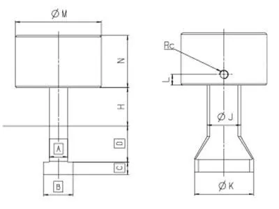
Specifications | M | N | Rc | L | J | K | H(Standard) |
FW2 | 50 | 55 | 1/8 | 12 | 18 | 38 | 25 |
FW4 | 76 | 65 | 1/4 | 15 | 25 | 55 | 30 |
FW6 | 80 | 70 | 1/4 | 15 | 30 | 64 | 30 |
FW10 | 100 | 75 | 1/4 | 15 | 40 | 78 | 40 |
FW16 | 130 | 80 | 1/4 | 15 | 50 | 88 | 50 |
FW25 | 150 | 105 | 1/4 | 15 | 60 | 98 | 50 |
Note: H is the thickness of the mold base plate matched with the standard hydraulic clamp and can be customized upon request.
- The electrical system is equipped with an OMROM programmable controller, ensuring safety and ease of use.
Reviews
There are no reviews yet.